

ST100
ST100 quick start
Get to know the ST100, prepare it with a SIM, check it powers up and read its LEDs. Then follow the installation manual to fit it in the vehicle.
Know your device
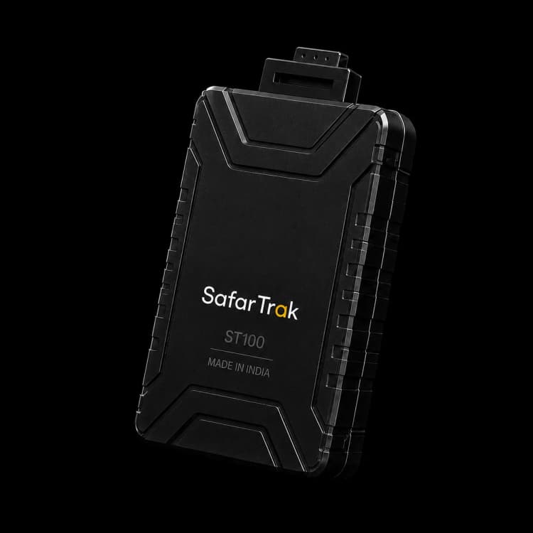
- Top face: two LEDs, GPS and GSM. The GPS antenna sits under this face, so it must point at the sky.
- Inside the flap: Nano-SIM slot, backup battery plug and a Micro-USB port for setup.
- Harness: one 9-pin connector with colour-coded wires.
Wire colours and pins
| Pin | Wire colour | Signal | What it is for |
|---|---|---|---|
| 1 | Red | VBAT | Power supply, 9 to 90 V DC (permanent +12 V / +24 V) |
| 2 | Black | GND | Ground (vehicle chassis) |
| 3 | Green | DIN (IGN) | Ignition input |
| 4 | Brown | DIN-1 | Digital input 1 (door, PTO, panic button and similar) |
| 5 | Yellow | CAN-H | CAN bus high |
| 6 | White | CAN-L | CAN bus low |
| 7 | Pink | 1-Wire D | 1-Wire data (temperature sensor or iButton driver ID) |
| 8 | Orange | 1-Wire P | 1-Wire power |
| 9 | Blue | AIN / DIN | Analog input (fuel level sensor), or a second digital input |
Only red, black and green are needed for a basic installation. The other wires are for accessories: door or panic switch (brown), fuel sensor (blue), CAN data (yellow and white) and a temperature probe or driver ID (pink and orange). Insulate and tie back any wire you do not use.
Wiring diagram
Detailed rules for each wire are in power, ignition and ground.
Insert the SIM
- Power off and open the flap
Disconnect power first. Lift the flap cover with a plastic pry tool, gently, so the clips do not break.
- Remove the top cover
Take the top cover off slowly to reach the board. Do not twist or pull it.
- Insert the Nano-SIM
Slide an activated Nano-SIM into the slot the right way round until it sits firmly.
- Check the backup battery plug
Make sure the internal battery connector is pushed fully home and no wire is pinched.
- Close the tracker
Refit the top cover and press the flap until it clicks. Check that it is sealed and not loose.
Power up and connect
1. Power it
On the bench, use a 9 V or higher DC supply, or a 12 V battery. Connect red and green to positive and black to negative. The LEDs start blinking once it has power.
2. Connect for setup
- Micro-USB: open the flap, connect the cable to a Windows PC and install the USB driver from SafarTrak support.
- Bluetooth: on by default. Pair from an Android phone in Bluetooth settings, then use the installer tools to check network and GPS status.
3. Configure
Trackers leave the factory with default settings. SafarTrak sets the server, APN and reporting settings for your account; technicians check them in the installer console. Configuration commands are only shared with authorised installers.
LED indications
| GPS LED | Meaning |
|---|---|
| Off | No GPS fix yet, or the tracker is in sleep or covert mode |
| On 0.5 s, off 1 s | GPS fix available |
| GSM LED | Meaning |
|---|---|
| Off | Not registered on the mobile network, or in sleep or covert mode |
| On 0.5 s, off 1 s | Registered on the mobile network |
| On 0.5 s, off 4 s | Data connection active and connected to the server |
| Fast flicker (0.1 s on, 0.05 s off) | Sending data |
LEDs not behaving as expected? See troubleshooting.
Stuck on site? Email support@safartrak.com or WhatsApp +91 95988 89988 (24/7) with the IMEI and a photo of the LEDs, or contact the team.